 Dual-frequency GNSS receivers are becoming more common, and you can now buy low cost L1/L2/L5 antennas. But it’s hard to find a GNSS antenna splitter that handles multiple bands; most of them have SAW filters for L1 only. I ran into that problem and designed a solution: the GUS or “GNSS Unfiltered Splitter,” which is what it says it is.
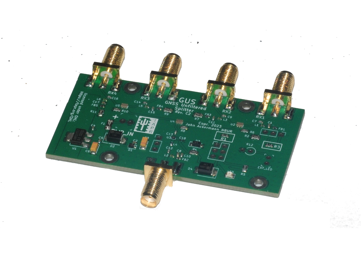
It has four output ports with SMA connectors and covers L1, L2, and L5 (in fact, it’s usable from 1 to about 1.7 GHz). Its LNA makes up for splitter losses and provides a net gain of about 7 dB. The outputs have equal time delays within a handful of picoseconds, but are not phase-matched.
The GUS does not have any bandpass filtering, so might not be suitable for use near high power transmitting sites. But in most applications, filtering beyond that provided by the antenna isn’t necessary.
The GUS can be powered from a receive, and voltage is passed through to power an antenna LNA. In addition, it can use external power and can handle inputs from 3.3 to 15 volts. An on-board regulator is available if the antenna requires lower voltage than the power source and antenna power can be disabled. In short, the GUS tries to support just about every receiver/power/antenna combination that’s out there.
The GUS is available from TAPR now at https://tapr.org/product/gus-gnss-antenna-splitter/
It’s fully assembled except for the RF connectors (which are included). A matching extruded aluminum case with endplates is available.
I put mine together today. I found it necessary to sand down the edges of the circuit board to get it to fit into the extruded case. I installed the board into the case and installed the five SMA connectors loosely into the end boards. With the top (or is it the bottom) of the extrusion removed I could use the end boards as assembly fixtures to properly space the connectors and solder them to the board.
I plan to replace the provided flat-head screws with some socket head button screws for a better look.
It fired right up without issue. I have a BG7TBL GPSDO supplying Port 1 with 5V and feeding the antenna. Two other ports are providing signal to two Bodnar GPSDOs. Lady Heather reports 40-60 dB SNRs on the nine birds I can currently see. I’m not equipped to use the other frequencies or satellites.
Hi, Thanks for the technical breakdown of this piece of equipment. My question is “What (application) would I use it for?”.
I have an outdoor GPS antenna, for precision time and such. However, I have multiple GPS/GNSS receivers that I use simultaneously. I either need one of these, an old HP box (Z3805A or similar) you might or might not find on eBay, or multiple GPS antennas.
It allows ‘phantom powering’ of an active GPS antenna, which can really only come from one place. that is if you have one receiver that powers an antenna, and you want to add another receiver, how do you ‘split’ then antenna, yet feed the power to the antenna via a Bias-T arrangement?
Bias-T is effectively built in, but it passes power from the designated receiver that can supply power.
George,
Thank you for your reply. Now that I understand the application, I may find the use for this with my Pluto and the Amateur Radio Astronomy project that I have planned.
73,
Bill